Looking at the vector diagram below, we see the four QPSK symbols and their properties as summarised in the table below.
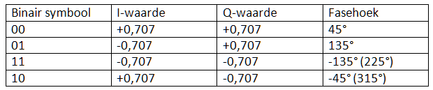
This table corresponds to the classic vector diagram of QPSK modulation, in which the symbols are evenly distributed over 360° with a phase distance of 90° between them.

In fact, the four points (clockwise, i.e. with increasing angle) lie at the corners: 45°, 135°, 225° and 315°.
However, when explaining differential QPSK (DQPSK), it is often clearer to refer to: 45°, 135°, −135° and −45°, which are mathematically completely equivalent.
Note on order and coding:
When we use the (mathematical) positive rotation (counterclockwise) and look at the symbols sequentially, we notice that the binary codes are not numerically ascending:
| Codes in counter-clockwise direction | Decimal value |
| 00 | 0 |
| 01 | 1 |
| 11 | 2 |
| 10 | 3 |
Several important features stand out here:
- The values 2 and 3 are swapped in relation to the classic binary sequence
- Symbols that are diametrically opposed (180° phase difference) have complementary binary codes : 00 ↔ 11 and 01 ↔ 10
- In the sequence 00 → 01 → 11 → 10 → 00 → …, only one bit changes per transition
- This property also applies to the transition from the last symbol back to the first
These properties define exactly what is known as a Gray code. In the case of QPSK, we therefore refer to a 2-bit Gray code.
When QPSK symbols are encoded in this way, it is referred to as QPSK with Gray coding — and this is exactly the encoding used in DAB and DAB+.
Why is Gray code used in QPSK?
The use of Gray code is not a coincidence, but a conscious design choice to minimise the error sensitivity of the system.
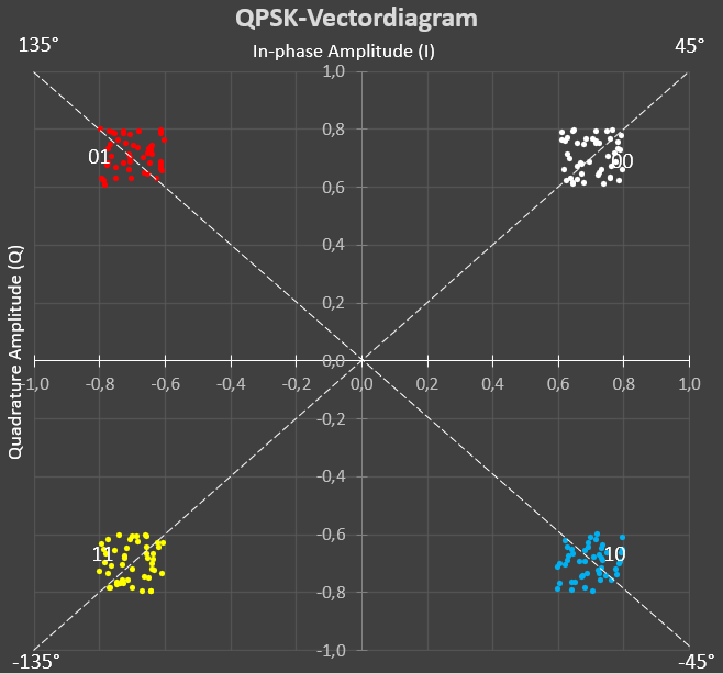
Looking at the vector diagram of QPSK, we see that:
- Symbols that are horizontally or vertically adjacent to each other are closest to each other
- Symbols that are diagonally opposite each other are much further apart
It follows that in the case of noise:
- Horizontal and vertical shifts are most likely
- Diagonal shifts occur much less frequently
By applying Gray code, the following applies:
- A horizontal or vertical error leads to a 1-bit error
- A diagonal error leads to a 2-bit error
Because the most likely errors affect only one bit, the probability of 2-bit errors is greatly reduced by applying Gray code. This is particularly important because forward error correction (FEC) works much more efficiently with single-bit errors than with multiple-bit errors.
Influence of noise on the vector diagram
Wireless transmission involves both:
- Amplitude errors on (change in the length of the vector)
- Phase errors (slight rotation of the vector)
As a result, the received symbols no longer lie exactly on the ideal points, but form a cloud around each ideal symbol.

As long as the received point remains within the same quadrant, the receiver can still detect the correct symbol.
That is why we refer to digital or discrete modulation: the exact position is less important than the area (decision plane) in which the point falls.
However, with increasing noise, the vectors may:
- First cross the horizontal or vertical decision lines
- Only cross the center point (diagonal boundary) in the case of much larger errors

Thanks to the Gray code, exceeding a horizontal or vertical boundary results in only one error bit. Even with significant noise, errors are therefore limited to 1-bit errors, which significantly increases the robustness of the system.
In summary
- QPSK uses four symbols with a phase spacing of 90° between them
- Gray coding ensures that neighboring symbols differ by only one bit
- The most likely errors therefore lead to minimal bit errors
- This increases the reliability and efficiency of error correction
- That is why QPSK with Gray code is the logical choice for DAB/DAB+